
ANSYS Mechanical: Strategies for modelling bolted connections
It can take many years of experience of both product knowledge and simulation techniques to understand where to compromise the simulation model to enable it to be solved in the computational resource available while maintaining a reasonable level of accuracy. Working with bolted assemblies is one area where this trade off is very apparent. Do you model the whole bolt, with washers and nuts, possible even the thread? Or do you use some level of abstraction, some representation of the bolt, which captures the behaviour of the bolted connection, but allows a much more efficient solution? We discuss some of the possible approaches below.
Many engineering structures are assemblies that are held together using bolted connections and it is quite normal for design engineers to build CAD models that contain many nut, bolt and washer sub-assemblies within a wider full assembly model. When we try to mesh such assemblies, we can often end up with very high element counts, resulting in many system equations and therefore excessive run times. Indeed, in such circumstances it is not unusual to produce a meshed model that is too large to be able to be handled, in a reasonable amount of time, by the computational resources available. Compromises must be made.

Do you actually need to model the bolts?
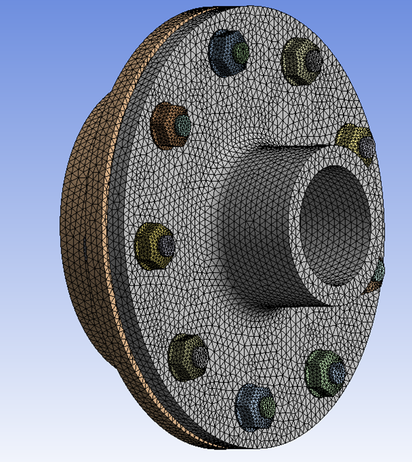
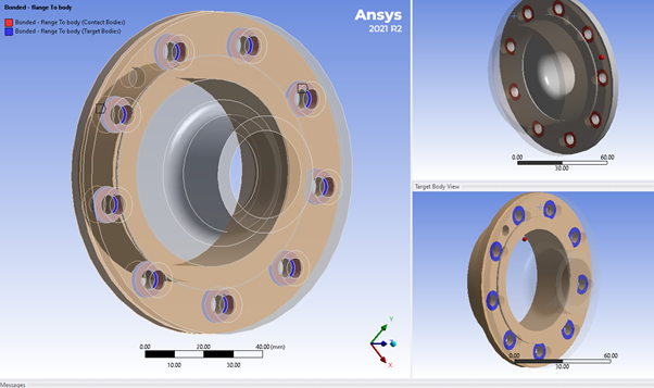
Figure 1: A flange assembly
Imagine the flange assembly shown in figure 1. This contains full representations of the bolts, nuts and washers. If we mesh this assembly as shown, we end up with 315000 elements and 948000 system equations. If we remove the nuts, bolt, and washer assemblies, then we have a model that has 117000 elements and 568000 system equations. A reduction of 38000 system equations to solve, resulting in a much more computational efficient model. As an engineer, you should ask the question “what is the purpose of the bolts?”. Remember a bolt is a fastener. It is used to “fasten” parts together. So, it may be appropriate to dispense with the nut, bolt, washer assemblies altogether and just use an alternative “fastening” method in Ansys.

Figure 2: Using bonded contact to join the whole of the back faces
In many cases the answer is yes. It is an engineering judgement call. If we imagine our flange assembly, the bolts exist just to hold the two flange back faces together. So, we could just connect the back faces using bonded surface to surfaces contact as shown in figure 2. Using this approach will maintain contact between the back faces. This would probably give an over-stiff model but would have the advantages of being a linear contact model, of not having to prepare the model in any way and being computationally inexpensive. If this model is used as part of a wider study, the results may be close enough to what we require. One downside to this approach is that you may not be able to easily extract bolt reaction forces that are often required for bolt sizing hand calculations.
If over-stiffness is a concern, then rather than used bonded contact for the whole of the flange back faces, we may choose to bond only the surfaces where the pressure from the bolt pre-tension effectively holds the mating surfaces in contact. This is often referred to as the effective pressure cone. Figure 3 shows a representation of the 30-degree pressure cone which if often used.

Figure 3: 30 degree pressure cone
(Image source https://mechanicalc.com/reference/bolted-joint-analysis )
By applying your chosen standard, you can modify your flange geometry and create a surface patch that represents the pressure cone area and use this to create the Ansys bonded contact regions. Figure 4 shows our flange assembly connected using bonded contact just at the effective pressure cone regions. This approach as the advantage of not being overly stiff as it allows the inter-bolt back flange faces to separate should the applied load enforce it. We are still not modelling the bolts assemblies and incurring the computational overhead that involves, and we are still performing a linear contact analysis, so run times should be relatively small. This approach also as the advantage of providing an effective area of bolt load that can be used to extract reaction forces for use in bolt sizing hand calculation. There is a small down-side to the pressure cone approach. The geometry may need to be modified beforehand as the pressure cone surface is unlikely to already exist. This can be done in the CAD system or using an Ansys Geometry prep tool such as Ansys Spaceclaim.

Figure 4: Bonded contact applied to effective pressure cone area only
You may want to enhance this approach further, by adding a frictional contact pair for the inter- bolt regions that will allow separation of these regions under tensile loading but will prevent penetration under compressive loading conditions. Beware though, once you add a frictional contact, this is a non-linear contact case, so your analysis will have an additional computational overhead.
In the physical world, bolt assemblies are only effective if they are appropriately pre-tensioned. So often in the simulation world we want to investigate the effect of the bolt pre-tension on the behaviour of our structure. In this scenario we still need to model at least a representation of the bolt.
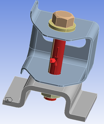
Figure 5: Bolt pre-tension load applied to a bolt shaft
Ansys Mechanical provides a simple tool for applying a pre-tension load. If you have a model that contains a full bolt assembly representation, then you can simply select the cylinder surface (or half surface) that represents the bolt shaft and attach a bolt pretension load. At solve time, Ansys splits the mesh at the bolt pre-tension location and overlays the cut surface with pre-tension elements and applies a compressive force. Figure 5 shows a bolt pre-tension load as applied to a bolt model.
If you examine the results from such a bolt-pretension load when applied to a full bolt assembly, you can see the cut faces pass through each other when you scale the deformation results. See figure 6 below.
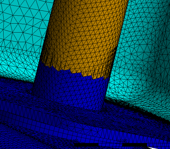
Figure 6: Bolt-pretension cut faces after solution
If we return to our bolted flange model, we can also model this assembly and include bolt-pretension without including the full bolt assembly model and the computational overhead that it incurs. We can replace the nut, bolt, washer assembly with a beam. Ansys Mechanical provides convenient beam connection technology under the connection branch of the outline tree. When we insert a beam connection, we attach one end of the beam to a surface representing bolt washer face and the other end of the beam connection to the face representing the nut washer face. The beam is a single element that has applied material and therefore actual stiffness and a circular cross section with a diameter to represent the bolt shaft. Once inserted a bolt pretension load can be applied to the beam in a similar manner as the full bolt model. See figure 7.

Figure 7: Bolt-pretension applied to a beam representation of the bolt.
When using a beam representation, at a solver level Ansys creates a spider constraint equation network to connect the ends of the beam to the flanges. See figure 8.
Using a beam connection retains the advantage of reducing the total number of system equations, whilst still allowing the ability to model the bolt pre-tension and stiffness. Note, however, that some geometry preparation maybe required to create the surface imprints that represent the area of the washer face that act as the mobile and reference connection surfaces for the beams.

Figure 8: Constraint equation network applied to a beam representation of a bolt.
Simulation of bolted assemblies are commonplace. CAD models often contain full 3D representation of the full nut, bolt and washer assembly and including this full 3D representation in your simulation may incur excessive computation overhead that in many cases may not be necessary. If the bolts themselves can be considered just a means of “bonding” parts together, try removing the bolts from the model and replace with surface-to-surface contact pairs. If you want to examine a more complex assembly interaction using bolt-pretension, then consider using “beams” instead of full 3D CAD representations of the bolts.
Pre and Post processing tool to create groups of rivets, bolt pretension, simplified bolts and advanced bolts with thread contact section. Bolt results can be evaluated according to Eurocode 3 including an automatic bolt report.

Written by Chris Dudding at EDRMedeso UK
For more information on these kinds of topics, check out our Ansys Mechanical page, or head to the events page to see what we’ve got coming up.
