Apply Robustness in Design to Overcome Uncertainty in Manufacturing

It’s no secret that manufacturing single electronic components produces deviations, and the assembly process can cause inconsistencies. That’s why we have guidelines like Six Sigma. The Six Sigma level of quality requires that a manufacturing process can produce products with no more than 3.4 defects per million. Six Sigma, otherwise known as robust design, encourages engineers to design products that are less sensitive to variation in manufacturing.
As electronic systems and components become smaller, higher in density, and more susceptible to heat, there are more unexpected interactions to account for, and it’s harder to predict how tolerances will impact design and manufacturing. By figuring out which production tolerances must be observed to ensure consistent quality, engineers reduce costs and defects, improve quality, and simplify workflows.

Picture: A production line worker in factory that produces electronics
Identifying the stochastic parameters during the manufacturing phase that can produce uncertainty and impact the quality of the final product, such as random environment variables or materials properties.
Injecting statistical data from manufacturing as probabilities in the simulation models for uncertainty quantification and prediction of the relative impact of those parameters.
Using artificial intelligence/machine learning (AI/ML) algorithms to iterate on the design and find optimal values with automated and systematic simulation processes.
Many companies use Ansys optiSLang for optimization, but here’s how some of them are using it to prove or improve the robustness of their designs and end products.
One major challenge in product design is identifying an optimal combination of function and cost; however, there are many approaches to accomplishing that, and each requires a different commitment in terms of development scope.
A global automotive manufacturer experienced this firsthand when comparing and evaluating design variants for the solenoids in their automatic transmission device design. The company used optiSLang and Ansys Workbench to establish a computer-aided simulation methodology that considered materials, tolerances, component topologies, geometric parameters, and manufacturing processes. This workflow generated a variety of solenoid designs in a short time with cost versus function optimization for each. By understanding the relationship between technical function and economics for each option, the team was able to select the most robust design.
Thin-film copper is common in the semiconductor industry due to its electrical and thermal conductivity characteristics. The function of a semiconductor depends on the performance of this metal under a wide range of temperatures. Typically, metallic thin film has different physical characteristics than bulk solids of the same material, so it behaves differently. To understand the stress-strain response of their thin-film copper and compare their reference experiment with simulated results, a semiconductor manufacturer used optiSLang to identify the correct material model to use.

Picture: A technician holds a semiconductor wafer at a manufacturing plant
“Manual” validation would take about three weeks to run 70 simulations, but after setting up the methodology, optiSLang ran 284 simulations in one day. The most time-consuming part of the process wasn’t the actual runtime; it was the analysis and decision-making around parameter changes that might lead to a better calibration with experimental results. optiSLang helped improve the quality and efficiency of the procedural results.
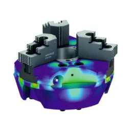
One company’s lightweight design of a lathe chuck supports maximum load capacity for customers looking for fast and efficient component production. Combining topology optimization (to identify the lightest suitable design) with parameter optimization (for the longest possible chuck life) created this robust result.
Multi-objective optimization with optiSLang revealed an optimal design with 30% less mass and 40% mass inertia.
Optimizing parameters in the jaw guidance area increased stiffness, improving the chuck’s core clamping function.
Finite element parameter optimization for reduced notch stresses and highest possible stiffness given constraints for lathe chuck.

Picture: Finite element parameter optimization for reduced notch stresses and highest possible stiffness given constraints for lathe chuck
Advanced driver-assistance systems (ADAS) help with emerging vehicle functions like automatic emergency braking, pedestrian detection, parking assist, and gaze detection. These systems are becoming increasingly complex as they assume more functions, so it’s more challenging to validate their safety. The mileage needed to assess the probability of system failure in field tests is practically impossible to achieve, so automaker Mercedes-Benz AG turned to simulation to identify critical traffic scenarios for safety function testing and evaluation using optiSLang.

Picture: A Mercedes-Benz cut-in scenario, with parameters of interest noted in the simulation environment
This method reduced the number of concrete traffic scenarios needed to prove a particular function and determine the risk per scenario in a fraction of the time. Mercedes-Benz AG was able to use this approach and their simulation results in their level-three ADAS certification proposal, which indicates qualifications for the design’s environmental detection capabilities.
Another use case of optiSLang includes planning and developing tolerance concepts for car manufacturing. In the automotive space, preparing for tolerance analysis is time consuming and sometimes fault prone, especially for body-in-white (BiW) structures, which consist of several hundred parts. At this stage of manufacturing, the car’s frame is assembled, but it’s unpainted.

For accurate tolerance analysis modeling and manufacturability, engineers need specific information (e.g., fixture concepts and joining locations) to define contact conditions, ranges, and measurements using simulation software. In practice, tolerance information for single parts, which is created during the product development process, is transferred to the simulation model along with tolerances for the manufacturing process and simulation parameters. optiSLang accommodates tolerance ranges, so it’s easy to consider multiple input variables in a tolerance sensitivity analysis to ensure a robust assembly.
For more information and examples related to simulation-driven optimization, robustness evaluation and uncertainty quantification in electronics and integrated circuit (IC) applications, register for our upcoming webinar “Designing for Six Sigma: Electronics Variation Powered by Parametric Variation.”
