Elevating Your Simulations Using Submodeling
Submodeling is a technique used in FEA that focuses on a particular part of a model to obtain results with greater accuracy in that area. Starting with a large model, the results are calculated and then analysed to identify an area of interest such as a stress concentrator. That area is then analysed with a more refined mesh.
There are a few different situations when you may think about implementing submodeling, the first scenario is when there are limited computational resources. There may be a limitation on your compute resources so you need to find a way to work around that limitation or you may not have access to a large cluster you can throw the model on and let it run. The smaller model size means allows the user to navigate computational bottlenecks.
A second scenario would be when there are tight project deadlines as it is possible to experience improved run times with submodeling. Running two models can be faster than running one model due to the smaller region with a dense mesh. This is important during the design process as you can run a greater number of iterations in less time.
Another use of submodeling could be throughout the design process of a product. During this period different designs are likely to be explored to discover the best solution. If you do this with a large model then geometric features such as fillets and chamfers may have to be removed to ensure that the meshing is not too detailed due to the larger size of the model. Using a submodel you can include these features and experiment with different fillet radii for example. These are not the only use cases for submodeling but hopefully, provide an insight into when it would be useful to implement the submodel approach.

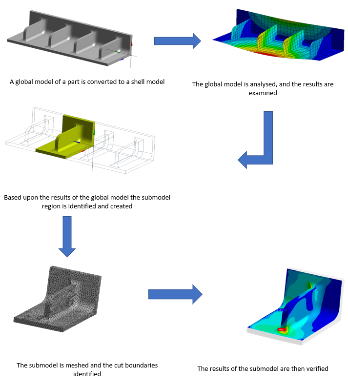
In this next section, we will run through the step that makes up the submodeling process.
The first step of the process is to create the analysis on the larger global model. This involves assigning materials, applying loads and supports and inserting result items. Once you have run the analysis on the global model you need to analyse the results and see where there are stress concentrations. Once you have found where stress is particularly high or identified where you would like to analyse it in more detail you can create the submodel.
The submodel can be created externally in a CAD package and imported in or it can be done in the geometry tools offered by ANSYS. Each way will provide the desired outcome. A good way to approach creating the submodel is to copy the global model geometry file and then split up the copied document and remove the unnecessary areas. This ensures that the geometry is in the correct orientation and geometric space. It is important when creating the submodel that the boundaries are not too close to the area that you want to analyse as it can affect results.
Once the submodel geometry has been created it can then be imported. Before you run the analysis you will need to ensure the assigned material is correct and apply any boundary conditions that exist on that part of the model. The important part of the submodeling process is to tell ANSYS where the model has been cut, this is done by applying cut-boundary conditions. This tells ANSYS to transfer the results from the global model to these areas so that interpolation can occur between them.
After the submodel has been set up and the cut boundaries have been identified, the analysis is run just like the global model. You will then get results on the submodel where the data has been interpolated between the boundaries so you will have contours across the geometry.
Finally, it is crucial to verify the submodel to ensure that the results match up with the global model. This is essential for two reasons, the first is that a cut boundary may have been missed or a boundary condition has been left off. The second reason is to make sure that the cut boundaries are sufficiently spaced to not interfere with the results. If they are too close to the area of interest then it will skew the results. Therefore it takes some engineering judgement to balance how close the boundaries can be placed to create the smallest model possible whilst not affecting the outcome. The model can be verified by comparing the results between the global and submodel. At the same locations, the results should be the same across the two models. You can manually probe the results in these areas but a better approach would be to create locations to ensure that the result is in the same place in both of the analyses.
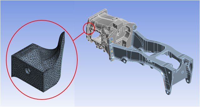
Here is a submodel example where the global model is a shell model and the local or submodel is a solid model. This example was included as it was particularly interesting to see a solid submodel of a shell model. This would allow the user to include geometric features such as fillets and explore designs as mentioned prior.