
Elliptical and other non-circular gears provide varying gear ratio. This changes the rotational velocity during one revolution. Also, the torque will vary significantly in the drivetrain. This can cause excessive vibration and noise which can greatly reduce fatigue life of components or even cause catastrophic failure if the loads become too high.
In figure 1 primary gear rotational velocity is increased and the varying gear ratio affects the rotational velocity of secondary gear. The elasticity in gears and shafts increasingly affects the secondary rotational velocity when the primary velocity increases.
Varying rotational speed causes interesting phenomenon especially with higher velocities. As the gear accelerates, torque is needed to rotate the inertias of the drivetrain and as the gear slows down the inertia changes the meshing of the gear switches to other side of the gear teeth. This also causes torque of the shaft to change direction during the revolution and will cause vibration and noise to system. Analysing which operating conditions are acceptable for the drivetrain is especially important for these types of systems.
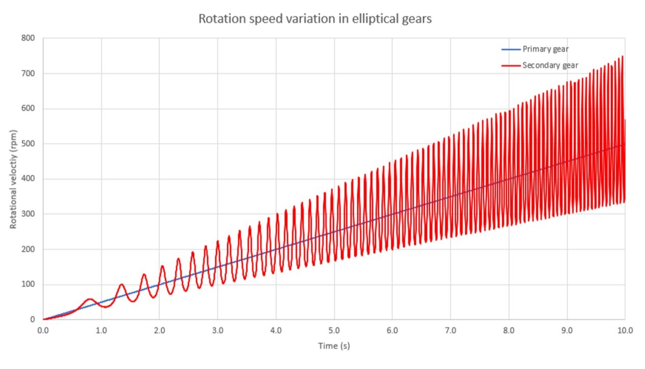
Figure 1. The effect of varying gear ratio to rotational velocity in elliptical gears.
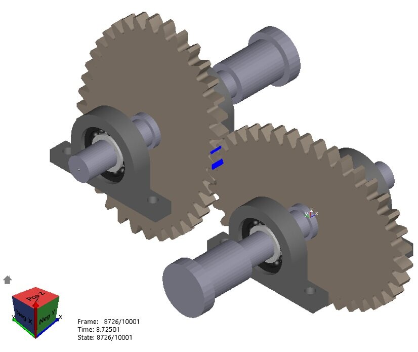
Figure 2. Simple elliptical gear system model in Ansys Motion with elastic shafts, bearings and bearing housings. Nodal contact force is displayed with blue lines.
Using Ansys Motion to model these non-circular gear drivetrains is efficient and straight forward. Model building starts from shafts. Shafts can be modelled from shaft dimensions and then the flexibility is automatically calculated, or you can import finite element mesh of the shaft if the geometry is complicated. Ansys Motion also has bearing library where you can pick bearing type and size you are using. The housing is a crucial part in these types of analyses and FE mesh of the housing can be imported to the model. In figure 2 there is a simple drivetrain system with two shafts, four bearings and bearing housings and one elliptical gear pair.
For elliptical gears, the torque can vary greatly as seen in figure 3 with two different rotational velocities. Slower velocity has relatively smooth torque with constant velocity and it tells that the operating conditions are good. The higher velocity shows that there are two positive and negative torque peaks which come from the varying gear ratio and because secondary shafts inertia tries to accelerate the system. This usually causes excessive vibrations in the drivetrain which decrease remaining useful life and can be heard as noise.
Ansys Motion is a multibody dynamics software which can solve many different problems from simple rigid mechanisms to complicated flexible rotating models. It has application specific toolkits for chain, link, drivetrain, and other systems. That is Motion!
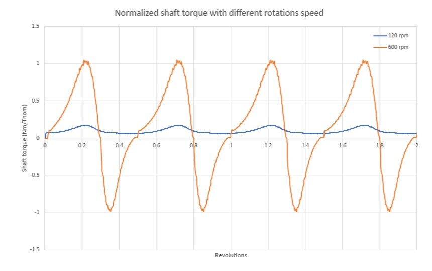
Figure 3. Normalized input shaft torque with two different rotational velocities over two revolutions.
