
How to reduce Saint Elmos Fire by using ANSYS Maxwell
How to reduce Saint Elmos Fire by using ANSYS Maxwell
How to reduce Saint Elmos Fire by using ANSYS Maxwell

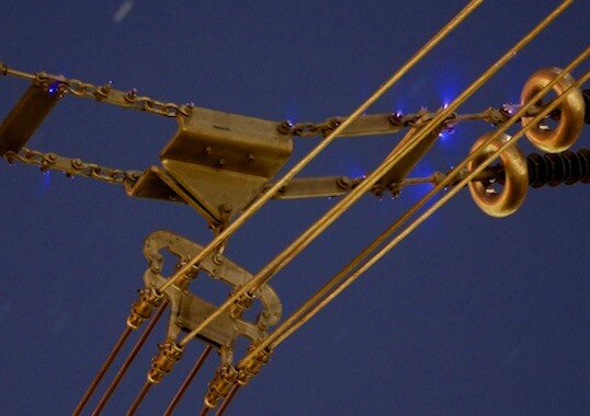
Figure 1. Saint Elmos fire in a transmission line in the upper right part of the picture.
The discharge can cause radio interference and audible noise in high voltage transmission lines and is therefore undesirable. The high electric field in the vicinity of the transmission lines causes free electrons to collide and ionize molecules and atom in the air. During the ionization, photons will be emitted and these photons cause the distinct discharge light called “Saint Elmos fire”. The electric field use to be highest at the attachment point between the transmission line and the insulants, this is where the transmission lines are closest to the grounded transmission line tower. One way to minimize the electric field at these points is to use Saint Elmos rings, see figure 2.
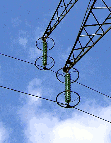
Figure 2. Saint Elmos rings in a transmission line, the rings reduce the electric field and thereby the Saint Elmos fire.
The placement of the Saint Elmos rings is of great importance and the field reducing effect can be simulated in ANSYS Maxwell by using parametric sweep of the placement. A CAD model of the insulant, wire, and the Saint Elmos ring is shown in the left part of figure 3. We are only interested in the relative change of the electric field, so the energized parts can for simplicity be set to the potential V = 1 and the grounded parts to V = 0. The field intensity is showed in the right part of figure 3.
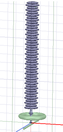
Figure 3. CAD geometry of the insulant, Saint Elmos ring and the conductor.
By using the animation function in ANSYS Maxwell and using animation the saved results in the sweep can be varied by a scale, see examples in figure 4 and figure 5. By varying the scale one can easily investigate where to place the Saint Elmos rings to minimize Saint Elmos Fire thanks to ANSYS Maxwell!
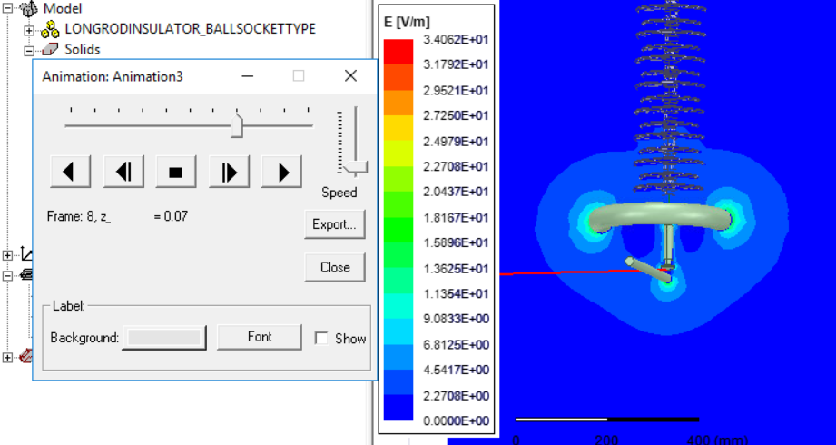
Figure 4. One of the sweep results, where the Saint Elmos ring is 7 cm above the wire.
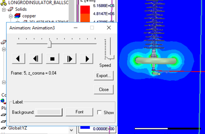
Figure 5. One of the sweep results, where the Saint Elmos ring is 4 cm above the wire.
