
Mastering Meshing for Mechanical Analysis
Meshing involves discretizing a geometric model into smaller elements, enabling numerical analysis. The choice of meshing technique depends on the geometry, analysis requirements, and computational constraints. The two primary types of meshes are:

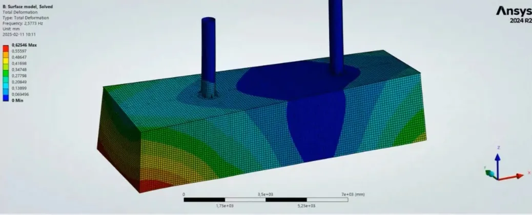
Surface model mesh
Advancements in meshing techniques have made it easier to create structured, high-quality meshes with minimal manual intervention. The introduction of Prime Mesh, Multizone, and Geometry-Preserving Adaptivity (GPAD) tools has significantly improved meshing workflows.
One of the significant updates in recent Ansys releases is the Prime Mesh method. This tool is an excellent alternative to traditional batch meshing and provides a more structured and high-quality shell mesh. It simplifies meshing by automating key steps, ensuring a conformal and quad-dominant mesh.
When working with surface models, the goal is to create a connected mesh while maintaining the integrity of the geometry. The Prime Mesh method streamlines this process by:
Beyond creating a quality mesh, Prime Mesh introduces several auxiliary tools to refine meshing workflows:
A practical approach to verifying shell meshing quality is through a modal analysis. This process checks the dynamic characteristics of a model, helping engineers detect potential connection errors. If no rigid body modes appear at or near zero frequency, the mesh is likely well-connected and suitable for further analysis.
For solid components, hexahedral elements (hex meshes) are preferred over tetrahedral elements (tet meshes) due to their superior accuracy and convergence properties. However, generating a well-structured hex mesh can be challenging.
Two commonly used methods for solid meshing are:
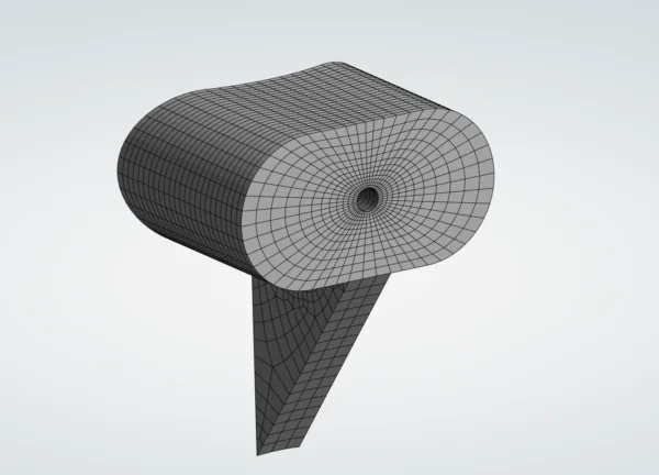
MultiZone Mesh example
Virtual Topology is a powerful tool for modifying the geometry without altering the CAD model. By introducing split faces and refining edges, engineers can guide the mesher to produce a well-structured grid. This process is especially useful when working with complex geometries that require specific element distributions.
Another way to improve mesh control is through Edge Sizing with Bias, which refines elements near critical features like holes while maintaining efficiency in less critical regions.
Adaptive meshing techniques help improve simulation accuracy without unnecessarily increasing computational costs. One of the newest and most powerful tools in this domain is Geometry-Preserving Adaptivity (GPAD), introduced in recent Ansys versions.
Why Use GPAD?
Unlike standard meshing methods, GPAD refines the mesh dynamically during the simulation. It adjusts element sizes based on strain energy criteria, ensuring that areas experiencing high stress receive finer mesh refinement.
Setting Up GPAD for Mesh Convergence
Mesh convergence studies are essential for ensuring that simulation results are independent of mesh size. GPAD simplifies this process by automatically refining the mesh in critical regions. The setup involves:
GPAD is designed for linear simulations, whereas NLAD is used for nonlinear cases. The primary difference is that GPAD refines the mesh while preserving geometric accuracy, making it ideal for capturing curved surfaces more accurately compared to NLAD, which simply refines existing elements.
1. Use Prime Mesh for Shell Models – It provides a more efficient way to generate conformal meshes compared to traditional batch meshing.
2. Utilize Multizone for Solid Meshes – This method ensures structured, high-quality hexahedral elements, avoiding issues with the hex dominant approach.
3. Leverage Virtual Topology for Complex Parts – Small adjustments to
topology, such as face splitting, can significantly improve mesh quality.
4. Apply Edge Sizing and Biasing – Helps refine critical regions while maintaining efficiency in less important areas.
5. Use GPAD for Mesh Convergence Studies – Adaptive refinement ensures accuracy without unnecessary computational expense.
6. Validate Your Mesh Connections with Modal Analysis – This technique helps
verify that connections are properly established, reducing errors in subsequent simulations.
Efficient meshing is fundamental to accurate and reliable simulations. By leveraging the latest meshing tools like Prime Mesh, Multizone, and GPAD, engineers can significantly improve their meshing workflows while maintaining high-quality results. These innovations reduce manual effort, improve accuracy, and optimize computational resources, making them invaluable for modern simulation tasks.
If you want to explore more about meshing techniques and best practices, consider joining advanced mechanical simulation training or reaching out for expert consultancy.
Efficient meshing is not just about following a process; it’s about mastering the art of balancing accuracy and computational efficiency.
Training solutions from EDRMedeso
Watch Coffee with an Expert: Meshing for Mechanical webinar on-demand
