Numerical study on the use of bentonite pellets as bulk material for oil and gas wells decommissioning using Rocky DEM
This blog post demonstrates the capability of the Rocky DEM software to adequately simulate the Plugging and Abandonment (P&A) process of wellbores using highly compacted bentonite pellets.
This blog post demonstrates the capability of the Rocky DEM software to adequately simulate the Plugging and Abandonment (P&A) process of wellbores using highly compacted bentonite pellets. The results show good agreement with experiments carried out at the Research Center for Rheology and Non-Newtonian Fluids (CERNN) at the Federal University of Technology – Parana (UTFPR).
Recently, due to the increasing number of wells reaching old age, oil and gas companies have been studying alternatives to improve quality and reduce costs in P&A operations. Such operations consist in performing workover for the permanent shut of the well. Among the several options available, bentonite pellets are an alternative material in place of Portland cement (the material used in traditional operations).
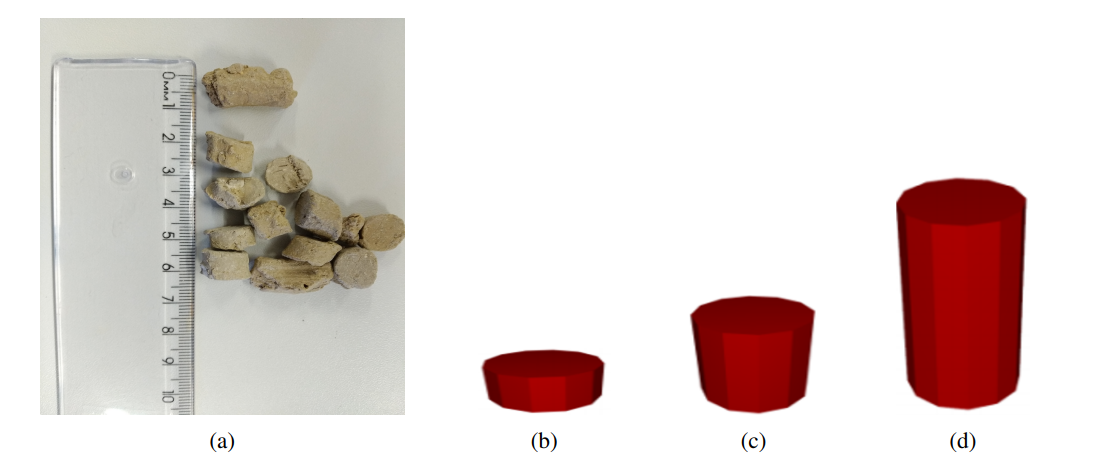
Bentonite is a natural clay, available commercially as pellets with a lower price than customary materials employed for P&A. Furthermore, the P&A process with bentonite is simpler, faster, and cheaper. It basically consists in the direct release of the pellets within the wellbore. A sample of the bentonite used in the present study is shown in Figure 1a. It can be seen that the particles have an almost-cylindrical shape, which makes it very ease to model within Rocky’s user interface. Figures 1b to 1d show the particles modelled in the software. They all had a diameter of 10 mm and varying aspect ratio (AR), defined as the ratio between their height and diameter. 0.5, 1.0 and 2.0 AR were used to represent the particles. The number of vertices of the pellets was 20.
Figure 1 – (a) Actual pellets obtained from the manufacturer. Pellets designed in Rocky’s interface. Aspect Ratios (AR) varied from (b) 0.5. (c) 1.0 and (d) 2.0.
Once the bentonite interacts with water, which might be present in some wells, it experiences two typical processes: first, a swelling that originates a pressure against the walls of the well, which must overcome the formation pressure, trapping the fluids within the formation and preventing the flow into the well.
Secondly, also owing to wetting, bentonite develops a strong adhesive force that consolidates the pellets and might make them bond to any surface present within the well. Owing to these two phenomena, premature plugging might occur if either the adhesive force or the fast swelling of the pellets lead to the formation of the plug before the material reaches the proper target zone inside the well.
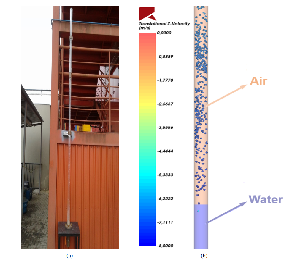
The first part of the work consists of calibrating the Discrete Element Method and the adhesive force by the reproduction of experimental results. The experimental unit is a six-meter-long acrylic tube partially filled with water, as displayed in Figure 2a. Bentonite pellets released at the top of the tower experience the water-triggering adhesive force and tend to plug the tube, generally in the air-water interface. The numerical domain, displayed in Figure 2b, resemble the experimental unit, with the plug being formed with the same characteristics found in the experimental device.
Figure 2 – (a) Acrylic column constructed in CERNN’s external area, in a previous stage of the project, with just three meters of height. (b) The same domain in Rocky, with details indicating regions containing air and water, respectively.
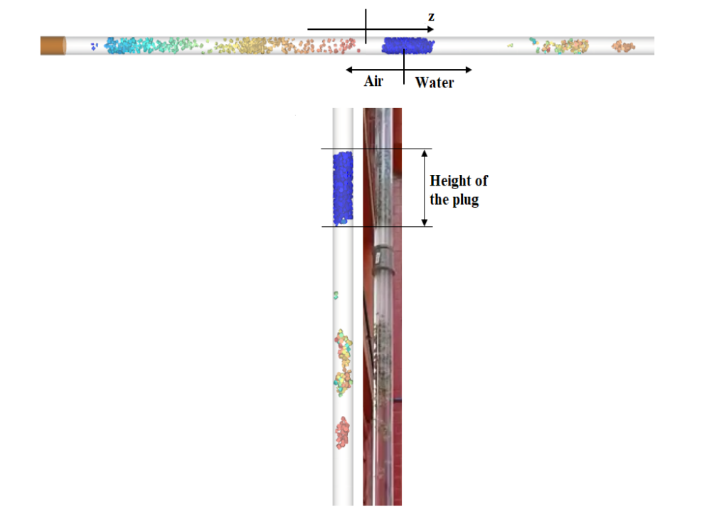
Figure 3 shows a comparison between experimental and numerical results. A high degree of fidelity can be obtained using Rocky DEM simulations. First, the height of the plug formed in the simulation is virtually equal to the height obtained experimentally in the acrylic column, which indicates that the Linear Adhesive Force Model can reproduce adhesive forces properly. Second, the pellets that do not form the plug and continue their downwards movement travel the same distance in both experimental and numerical studies, which indicates that the one-way coupling is capable enough of representing the particle behavior in this particular case.
Figure 3 – Comparison between results obtained numerically and experimentally. A high degree of fidelity is obtained with Rocky DEM.
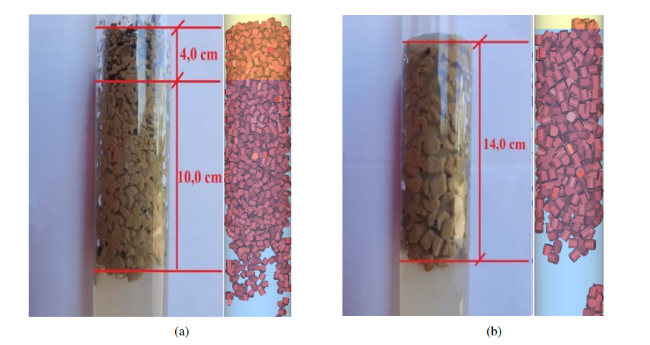
Figure 4 highlights the aspect of plugs formed with pellets of 4.76 mm and 6.40 mm size, both experimentally and numerically. in Figure 4a, 4.76 mm pellets form a plug that has some pellets that do not touch the water. The higher contact area of these pellets, along with their smaller momentum tend to induce the formation of the plug more easily. The height of pellets inside and outside the water again emphasizes the capabilities of Rocky DEM’s adhesive force model. Figure 4b shows the results obtained for 6.40 mm pellets. Since the total area available for contact is smaller for this graulometry, the plug is formed completely inside the water.
Figure 4 – Plugs formed experimentally and numerically for (a) 4.76 mm pellets. (b) 6.40 mm pellets.
Finally, trends regarding plug formation for each one of the granulometries used is shown in Figure 5. The figure 5a shows the plug formed for 4.76 mm pellets. As mentioned above, part of pellets remain outside of the water, due to the great plugging tendency of smaller pellets.
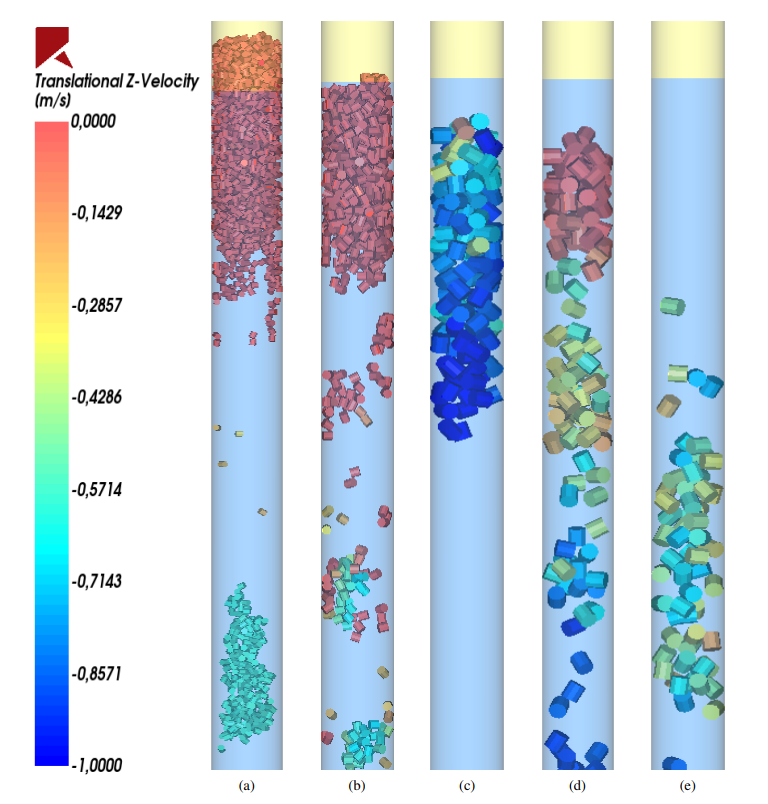
Figure 5b shows 6.40 mm pellets forming a plug completely localized within the water. When bigger pellets, with a diameter of 12.70 mm are injected within the well, the tendency for plug formation decreases: smaller contact area and bigger weight of the particles are responsible for this trend. Figures 5c to 5e show the time evolution of a plug formed by 12.70 mm pellets: the particles enter in the water, reach a state of rest, shown in Figure 5d, but, due to their weight, they detach from the walls, collapsing the plug (Figure 5e).
Figure 5 – General trends obtained in the simulations. (a) 4.76 mm particles enter in the water and form a plug where part of pellets stay out of the water. (b) The plug originated from the 6.40 mm pellets is completely located within the water. (c) 12.70 mm pellets enter in the water. (d) For a brief moment, a structure similar to a plug is formed. (e) After a few moments, the plug collapses.
The simulations carried out using Rocky DEM were capable of reproducing experimental studies and also agreed with trends mentioned in the literature. With a calibrated model, it is possible to predict phenomena regardind oil & gas wells decommissiong before actually abandoning them, which is believed to be the first numerical tool regarding this theme.
Written by Roderick Gustavo Pivovarski, Researcher at Laboratory of non-Newtonian Fluid Flow (LabFlow) – UTFPR. Mechanical Engineer graduated from UTFPR with a Master’s degree in progress at the same institution. Member of the Laboratory of non-Newtonian Fluid Flow – LabFlow of the Research Center for Rheology and non-Newtonian Fluids – CERNN, located at UTFPR. He works with application of CFD-DEM methodology for simulation of liquid-solid flows present in the petroleum industry. He has worked in research related to gravel cleaning in horizontal well drilling operations and prediction of premature plug formation in onshore well abandonment operations using bentonite.
We use cookies to enhance your browsing experience, personalize content and ads, analyze site traffic, and improve our services; by clicking "Accept," you consent to our use of cookies, and you can manage your preferences or learn more about our cookie policy on our Privacy Policy page.
Functional
Always active
These cookies act as personal helpers, enhancing your browsing experience by remembering your preferred language, location, and settings. They're completely anonymous and solely improve your time on our website, ensuring seamless navigation and personalized features like chat services and saved preferences.
Preferences
The technical storage or access is necessary for the legitimate purpose of storing preferences that are not requested by the subscriber or user.
Statistics
The technical storage or access that is used exclusively for statistical purposes.The technical storage or access that is used exclusively for anonymous statistical purposes. Without a subpoena, voluntary compliance on the part of your Internet Service Provider, or additional records from a third party, information stored or retrieved for this purpose alone cannot usually be used to identify you.
Marketing
Marketing cookies are used to track visitors across websites. The intention is to display ads that are relevant and engaging for the individual user and thereby more valuable for publishers and third party advertisers.