
Parametric ROMs (Reduced-Order Models) from Fluent steady state analyses

You produce the ROM by learning the physics of a given FOM (full order model) and extracting its global behavior. The ROM is created by advanced mathematical methods to combine the 3D (or 2D) solver result snapshots from a set of design points into a standalone digital object. Thereby, the final ROM can be utilized outside of its production environment for near real-time analysis. Examples of areas where ROMs may be used are:
to drastically speed up 3D simulations where there are no changes in the geometric design (ROM for 3D)
for performing efficient and accurate system simulation (ROM for Systems and digital twins)
to support non-traditional users to explore the design space (ROM for simulation democratization)
as physical plant models in the design, verification and operations of control systems, to enhance their precisions (ROM for controls design, ROMs “inside” controls)
NOTE: ROMs are Design-dependent, they are NOT generic libraries and must be generated for each geometrical design.
In Workbench there is a very efficient workflow to create a ROM from a FOM with just a few user interactions needed. The final 3D ROM file can be exported in standard formats (including FMU-format) that can be imported into hundreds of software tools, including Ansys Twin Builder (for creating a digital twin of a system). It can also be used with Ansys 3D ROM viewers so you can visualize design ideas almost instantly.
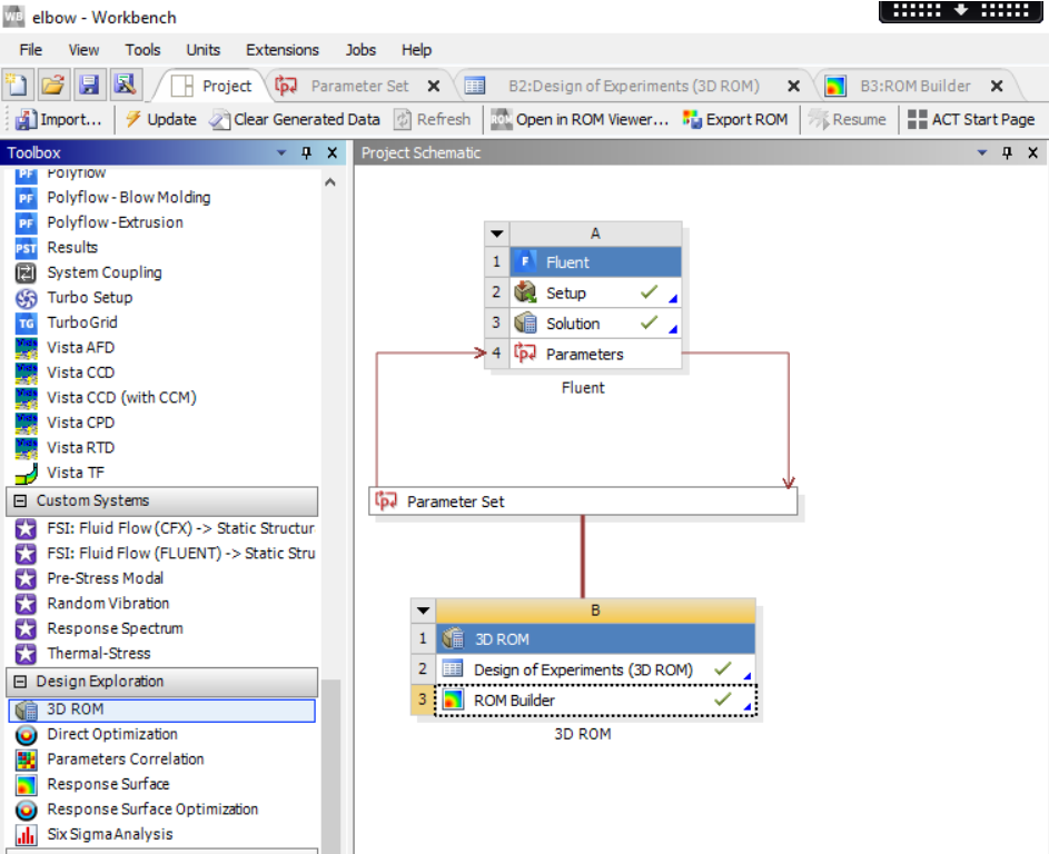
Figure 1: The ROM Builder workflow in Workbench. Just drag and drop to the project and follow the prescribed workflow of defining the DOE and ROM production.
You use a DesignXplorer 3D ROM system to drive ROM production from either a 2D or 3D simulation. In the Workbench Toolbox, the 3D ROM system is visible under Design Exploration (see Figure 1). A 3D ROM system is based on a Design of Experiments (DOE) and its design points, which automate the production of solution snapshots and the ROM itself.
You define the input parameters (see Figure 2) and content of the ROM in the simulation environment (see Figure 3), which is currently limited to Fluent. While ROM setup is specific to the ANSYS product, the ROM production workflow is generic. This means that as ROM support is extended to additional ANSYS products in future releases, the steps that you take to produce a ROM will be the same in all simulation environments.
Because ROM production requires several simulations, this stage can be computationally expensive (but no user work is needed). However, once the ROM is built, it can be utilized at negligible computational cost.
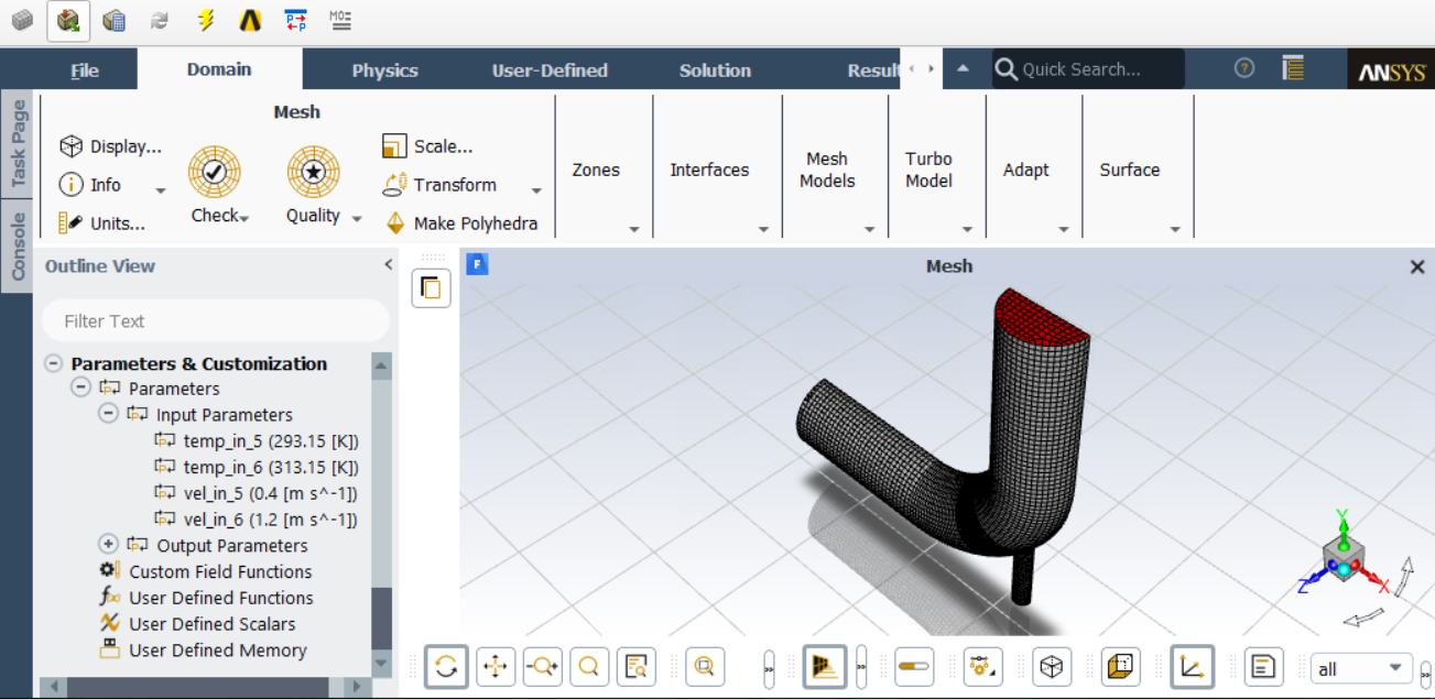
Figure 2: The definition of input parameters in Fluent.
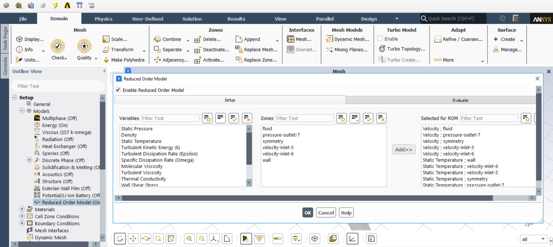
Figure 3: The setup of the ROM production in Fluent. ROM modelling needs to be enabled (left) and content of the ROM defined (right), by just a few quick operations.
The workflows for utilization of ROMs can differ from one application to another. Currently you can export the Fluent ROM as either a ROMZ file or an FMU 2.0 file, depending on which utilization environment is targeted.
A ROMZ file is a compressed package containing the data and libraries that allow the ROM to be utilized in the standalone ROM Viewer (see Figure 4). A ROMZ file can also be imported into Fluent in Workbench so that results can be evaluated directly in Fluent.
An FMU 2.0 file is similar to a ROMZ file as it also contains the entire ROM. This file can be imported into ANSYS Twin Builder, where it can be used as a part of a system simulation.
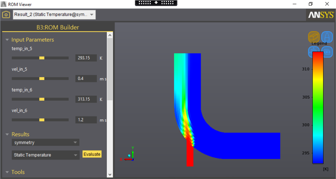
Figure 4: Example of ROM utilization in the ROM Viewer. The input parameters can easily be changed (highlighted in red colour rectangle) with instant impact on the result view.
