
Non-Linear Contact in Structural Static Simulation: Strategies for Obtaining Convergence
We often see some of our customers struggling with convergence issues when using non-linear surface to surface contact on structural static simulations. ANSYS provides a number of tools which can be used to help obtain convergence. We discuss some of them in this Blog.
Stability is one of the main issues. By stability, we mean is the model stable? Is there a theoretical numerical solution to the problem we are trying to solve? One of the biggest problems we encounter is rigid body modes that exist in the assembly model.
In a structural static simulation, you are prescribing some external loads to the model and trying to establish a static solution, so from Newtons laws we know that any force that is applied should have equal restraining forces. In a single part model, the restraining load is supplied by the prescribed constraints or supports. In assemblies, often the restraining load on an individual component is supplied by the interaction with the surrounding parts, I.e. by the contact in the model. Stability is best achieved by ensuring that all the parts of the model are always in contact.
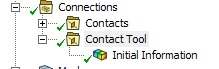
Quite often when assembly models are imported into ANSYS Mechanical from the CAD system, there are small gaps that exist between surfaces where the intention is that the surfaces are coincident or in contact. These gaps are often unintentional and due to the tolerances used in the CAD system. These small gaps, may result in parts not been in contact at the start of the simulation, resulting in rigid body modes and failure to provide a solution. ANSYS provides a contact tool, to check for these small gaps.
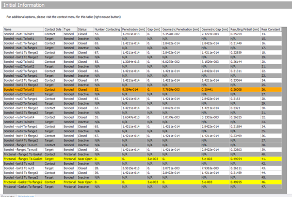
By calculating the initial information, ANSYS can display those parts that have small gaps that can cause convergence or solution issues. Below we can see those contact pairs in yellow that are initially open.
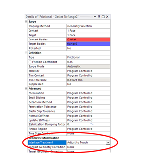
For those contact pairs that are initially open, but the intention was for these pairs to be coincident, ANSYS provides a convenient method to close these small gaps called interface treatment. Interface treatment allows the user to offset the point on the contact surface at which contact detection takes place, therefore allowing the user to effectively tell ANSYS to ignore the gap. The interface treatment option allows the user to insert an actual value, but also has a convenient setting of adjusted to touch. Setting these problematic areas to adjusted to touch will significantly improve stability of the model.
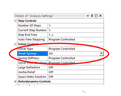
What happens if the gaps are intentionally included in the model and are too large to offset using the interface treatment? In this case we must try and reduce the rigid body modes in the free component. One method of doing this is by using artificial stiffeners such as springs or dampers. If you apply weak springs to the model, these springs add a small restraining force to any applied load. If you combine weak springs with a slow or small application of load, you can achieve a stable solution. As you increase the load, the assembly will displace under the balance of the springs until full contact is established and then the full load can be applied. To activate weak springs, toggle the option under analysis settings.
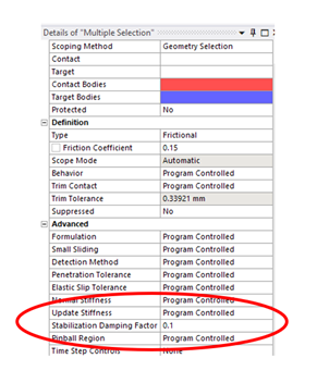
Another form of stabilisation is to switch on contact stabilisation. This will add artificial damping to the model to provide some artificial stiffness to the structure and allow a solution. When used with slow or incremental loading, weak springs and stabilisation have a similar effect, but using different methods. Weak springs add an artificial stiffness that is proportional to the displacement and contact stabilisation (damping) provides stiffness that is proportional to the pseudo velocity. Remember adding any sort of stiffeners can affect the accuracy of the solution. So care should be taken to ensure any values used are small enough to be negligible.
This is the old school approach. If intentional gaps exist in the model and are large enough to make one uncomfortable with the “adjust to touch” interface treatment and the idea of introducing artificial stiffeners to the model is a little off putting, displacement control provides another option.
With displacement control, the technique is to use a two-step simulation. In the first step, you apply a small finite displacement to the components in the model, to bring the whole of the assembly into controlled contact. Then in the second simulation step, once contact has been established, you remove the displacement and replace it with the actual load case.
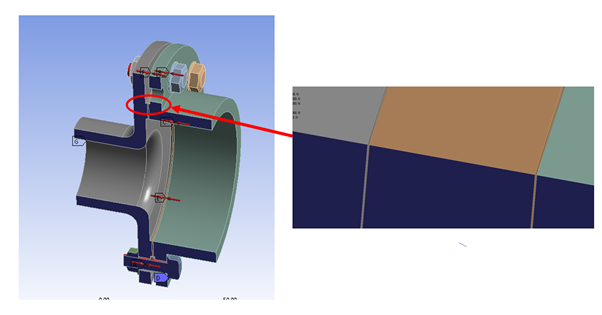
In this model, there is a 0.005mm gap that exists either side of the gasket (shown in bronze below).

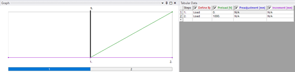
To obtain a stable solution, we supply a displacement control of 0.01mm to bring the assembly together in the first load step. And then we remove/de-activate the displacement in the second load step.
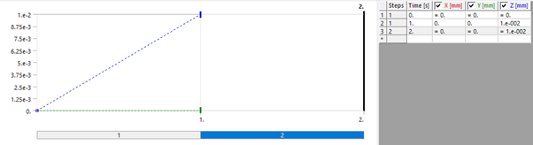
And for the actual loading, in this case 1000N bolt-pretension, we apply in the second load step.
Using displacement control is very robust method and can provide stability for a whole range of non-linear surfaces to surfaces assembly model problems.
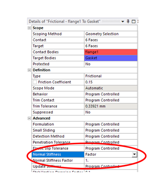
Contact convergence problems are not confined to issues regarding rigid body modes at the start of the simulation. Sometimes a user can experience convergence issues during solution. Contact is a changing status non-linearity. Binary in nature. If it closed there is contact and transfer of compressive load, if it is open there is no contact, no transfer of compressive loads. On or off. Numerical methods do not like changing status conditions. To handle this, the default contact formulation in ANSYS is augmented Lagrange. Augmented Lagrange is a penalty-based method, which converts this on/off status to a finite, but small transfer od stiffness once parts come into contact. Essentially, when using this method, a small amount of penetration is allowed, and that penetration is opposed by applying an underlying stiffness. As a user we have control over both the penetration and the underlying stiffness that ANSYS uses, we can make use of this to assist convergence. I do not want to discuss the theory of the penalty method in this blog, please take a look at the training or reference material in ANSYS, however as a general rule if the contact is too stiff, then force convergence is slow and excessive computational overhead can follow. Relaxing the stiffness (to a point) can achieve better convergence behaviour albeit at a compromise to accuracy. The contact stiffness value can be manually adjusted using the normal stiffness value for the contact pair.
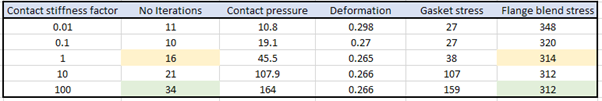
Below is a study of contact stiffness (FKN) vs Number of iterations to converge vs Accuracy. In this example we can see that there is very little difference in the accuracy of the results in the “flange blend” region of interest, for a reduction in contact stiffness factor from 100 to 1, but the convergence is achieved with half the number of equilibrium iteration.
Contact in ANSYS is a complex subject. Indeed, EDRMedeso can provide a full two-day training course just on contact technology. In this blog, we have just tried to give some pointers to tackle the most common convergence issues we see our customer are experiencing.
For demonstration of some the above techniques, please see the EDRMedeso webinar, Contact: Strategies for obtaining convergence.
