
Making Quasi-Static Simulations Simple with Ansys LS-Dyna
Quasi‑static analysis in Ansys LS‑DYNA is widely used to model slowly applied loads where inertial effects are negligible. Engineers across industries such as automotive, consumer products, and industrial equipment rely on quasi‑static simulations to accurately predict deformation, stress distribution, and contact behavior under static‑like conditions.
Although Ansys LS‑DYNA is best known for explicit dynamic simulations such as crash or drop testing, its explicit solver can be highly effective for quasi‑static analysis when the right modelling techniques are applied. This article explains how to run accurate quasi‑static simulations in Ansys LS‑DYNA, covering solver behavior, damping strategies, mass scaling, time control, and best‑practice setup to ensure stable and efficient results.
Ansys LS‑DYNA is a full multiphysics simulation solution. Originally developed for short‑duration dynamics using explicit time integration, it now supports implicit solvers, CFD, thermal, electromagnetic, NVH (noise, vibration, and harshness), and other advanced physics.
For quasi‑static analysis in LS‑DYNA, the explicit solver is often surprisingly well‑suited. While explicit solvers are typically associated with highly dynamic events, carefully controlling loading rates, kinetic energy, and time step size allows the solver to behave like a static solution while retaining its robustness and speed.
Quasi‑static simulations rely on solving equations of motion over time. Two main time‑integration schemes are used:
Implicit methods solve future states iteratively. They are unconditionally stable and support longer time steps, but they can struggle with nonlinear materials, contact, and convergence issues.
Explicit methods solve the current state directly and avoid iterative convergence. Although they require smaller time steps for stability, explicit solvers become well suited for quasi‑static analysis when loads are applied slowly enough to minimize inertia and kinetic energy.
With careful setup, explicit quasi‑static simulations in LS‑DYNA can deliver stable, accurate results even for highly nonlinear problems.
Achieving true quasi‑static behavior requires thoughtful model setup:
A common workflow is to begin with a short analysis to debug the model, then progressively increase the simulation end time. If results stabilize and no longer change with longer load durations, the solution has likely reached the quasi‑static regime.
Explicit solvers are limited by the smallest element size in the mesh, which controls the stable time step. Mass scaling in LS‑DYNA artificially increases element mass, reducing wave speed and allowing longer time steps.
When applied carefully and monitored closely:
As long as kinetic energy remains small compared to internal energy, mass scaling is a powerful tool for accelerating quasi‑static simulations.
Many engineering assemblies include preloaded components such as bolts, press fits, or clamped interfaces. Accurately capturing preload effects is essential for realistic quasi‑static analysis.
Two common preload methods are used:
Direct preload in the main analysis
Simple to apply but may introduce transient effects.
Dynamic relaxation
Runs a short pre‑analysis where loads are applied and allowed to settle before the main simulation starts. This produces cleaner initial conditions and more stable results.
Dynamic relaxation can be performed using either explicit or implicit solvers and is often preferred for complex preload scenarios.
Sequential Loading and Restart Analysis in LS‑DYNA
Engineering problems frequently involve stepwise loading conditions such as preload, side load, unloading, and reloading. Restart analysis in LS‑DYNA allows each load stage to build on previous results efficiently.
LS‑DYNA supports:
This approach improves workflow flexibility and reduces model re‑setup time during design iteration.
Ansys Workbench provides a structured environment for building quasi‑static LS‑DYNA workflows:
Workbench also enables traceable restart workflows, simplifying complex sequential simulations.
Post‑processing is critical to confirm quasi‑static behavior:
Comparing simulations with different load durations (for example 0.1 s, 0.5 s, and 1.0 s) helps identify when static‑like behavior is achieved.
Using explicit solvers for quasi‑static analysis offers key advantages:
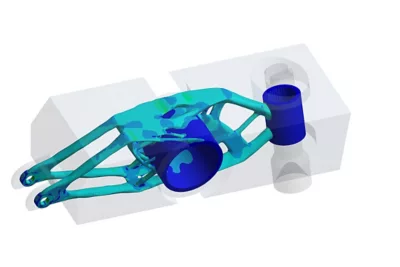
Applications include bolt modeling, rubber deformation, structural collapse, crash safety components, and ROPS (rollover protection system) simulations.
With controlled loading rates, smart mass scaling, and restart analysis, Ansys LS‑DYNA explicit solvers provide a robust and efficient solution for quasi‑static analysis.
Learn more
